G&G L85A2 Installation Guide (Pending Update)Updated 4 years ago
DG L85 kit for Army / G&G L85 AEG body.
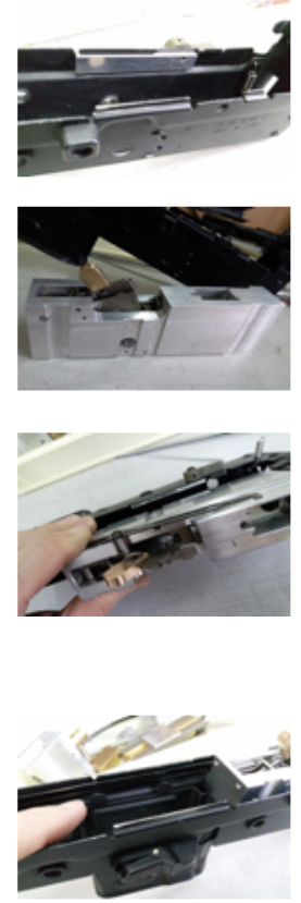
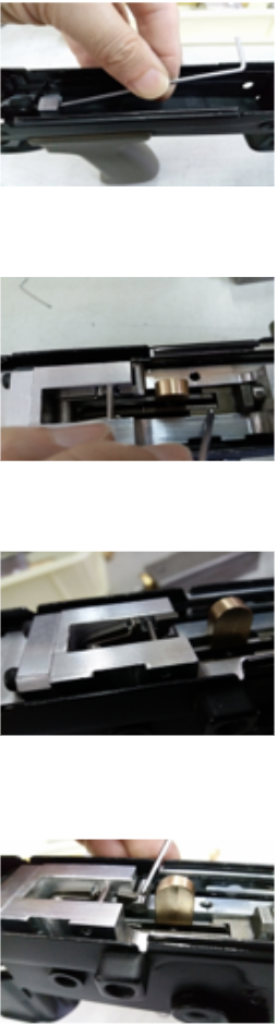
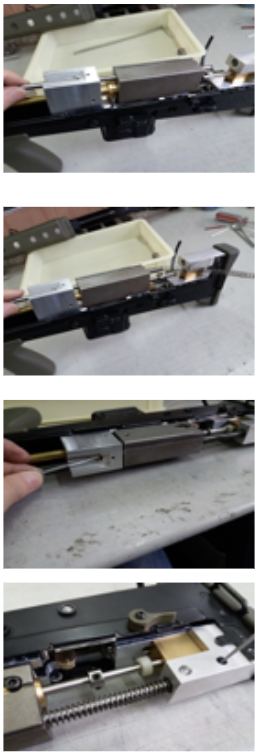
Remove the 3 caps inside the body.
1. Cut the scope mount rear hole to the same height as the receiver
2. Cut the inner top part as shown in the picture
3. Drill a hopup hole
4. Cut the outer barrel
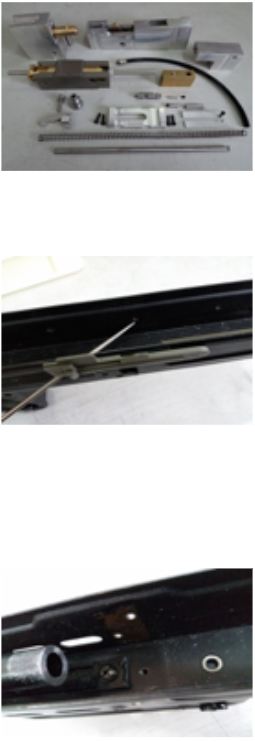
Drill the weld points on both sides of the body to take the block out.
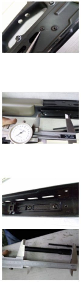
The distance between the hop up hole edge to the scope mount edge is about 48.2mm. The hole diameter is about 3mm.
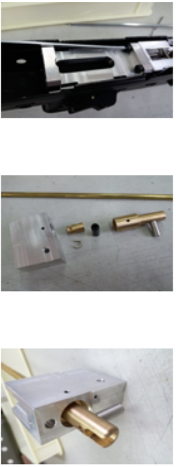
The upper is done.
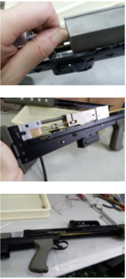
Disassemble the lower frame. Drill a hole by the bottom at rear to let the tubing out. You can follow the trigger box to mark the hole.
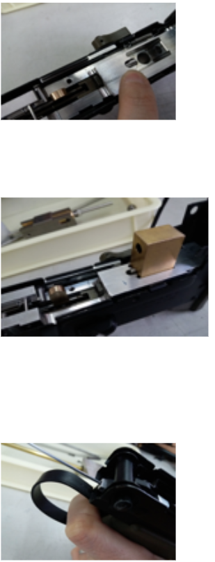
Put the trigger adjustment block into the lower frame.

Place it in this direction. Easy to put into it. Push the block flush with the flat surface.
Tighten it up from the bottom.
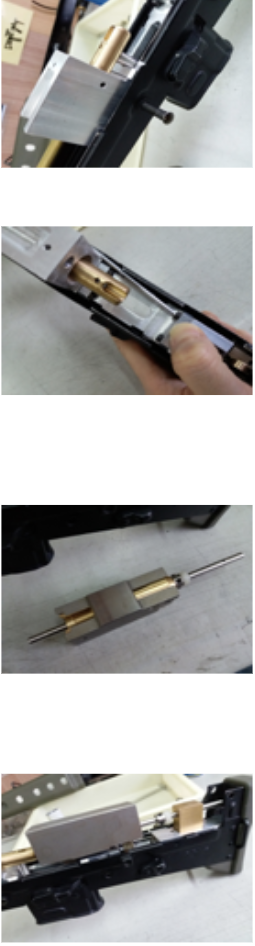
The trigger adjustment block has been installed. No need to adjust the trigger at this moment.
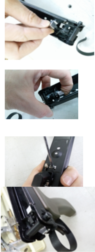
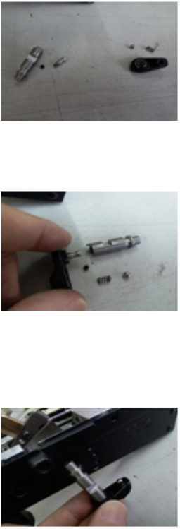
Put the trigger lever pin on. Drill the original hole on the long stock trigger plate to about 2.4mm.
Tighten the pin as shown.
Put the trigger guide plate on. 3 mm for Army receiver, 2mm for G&G receiver.
The direction is shown in the photo.
The trigger box is pre-assembled. Pull up the semi / full plate. Shown in the photo.
Put the trigger box into the body. The trigger pin MUST be put lower than the triangle plate of the box.
ARMY body is loose, G&G may be tight to get in. Be careful of the two tips. You may think the box does not fit, but the two tips might just be jammed on long plate. You can drop the box in without the pin to try it first.
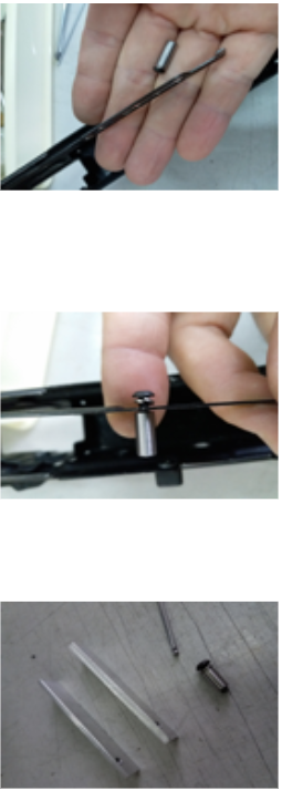
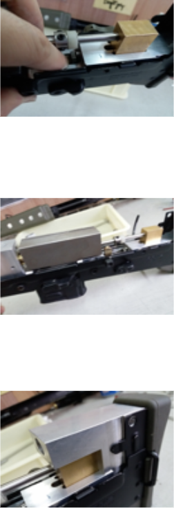
Selector assembly
Right hand side is ARMY stock parts.
Assemble the pin by the selector button, then secure the rod.
Put the selector in carefully. The semi / full plates should be up as shown in the picture.
Lock the selector. The lock pin has a different direction for use. Small tip facing down is for ARMY, small tip facing up is for G&G.
Shown in the photo is for the G&G receiver.
Place down the semi / full plates and use a rod to link up the trigger return spring as shown in the photo. Now you can tighten up the lower screw of the butt plate, it locks to the trigger box (not too tightly). The selector may be hard to move if so. You can check the selector after you put the screw on.
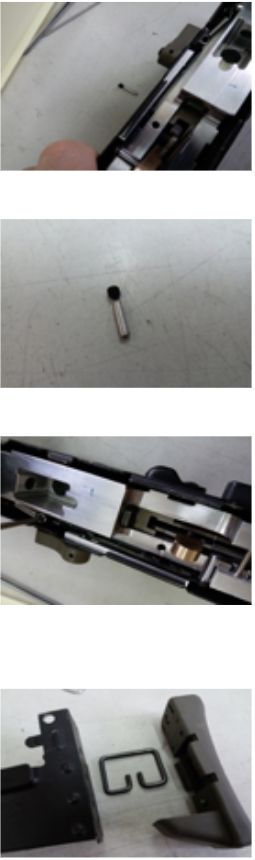
Put the valve pin in the box. Put the valve in the box.
You need to move the valve-push plate forward to let the valve pin forward, then the valve can sit at the bottom position.
The trigger is now adjustable. Front screw is for pull limit.
The back screw is for the trigger return limit, so this is to adjust the space to know how far to open the valve.
Be careful that if you adjust the trigger return limit too close, it may affect the motion of the full-auto plate.
The 2mm pin in the trigger box is to avoid the prevent the triangle plate from moving up, scratching the bottom surface of the steel bolt. And this is also the pull limit of the trigger.
When you adjust the trigger limit, you can see the distance to the triangle plate of the box.
Link up the plate. No need to tighten it up at this moment.
Assemble the hopup block with the inner barrel.
Secure the hopup chamber and the chamber block. You will want to align it properly to achieve better feeding.
Put the whole chamber set in the body, and secure the pin. Insert the two screws to link up the plate.
Push down the plate and apply a bit of pressure. Put your finger in the middle of the two screws, then tighten them to keep the plate flat. Then secure the front two screws.
Check the bolt assembly to make sure the white spacer and one more brass spacer is inside the bolt tank.
Put the bolt assembly on. Be careful not to bend the shaft. Now the valve should not be sitting at the bottom position.
Pull the valve-push plate to allow the valve pin to move forward, then push the valve down. Be careful not to bend the shaft.
After the valve is sitting at the bottom position the bolt should be the same as shown in the photo. You can pull and push the bolt assembly and it should be very smooth.
Put the recoil pin block on.
Insert the recoil pin from the front hole of the chamber block. There is a gap by the pin rear; it is for securing the pin inside the recoil block.
Before the pin is locked, insert the recoil spring from the bolt end as shown in picture. Hold the pin and continue to press the spring until the rear tip goes into the recoil block.
Check that the pin is touching the rear end of the recoil pin block. Secure the recoil pin.
Pull back the bolt carefully; rotate and pull the recoil pin to make sure it will not loosen.
Now you can test semi / full auto, and check any other positions to make sure it is working before you slide the upper frame on. You can also put the upper screw of the butt plate on.
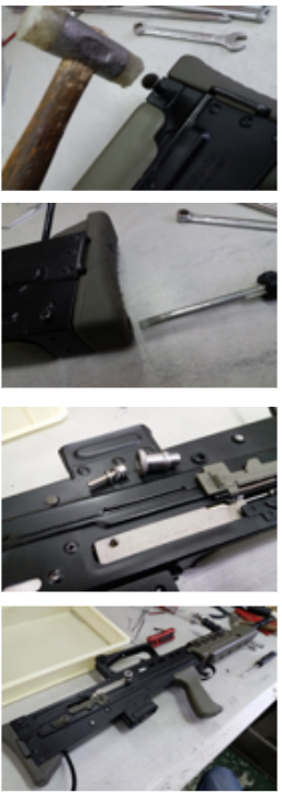
Slide the upper frame on from front to rear.
Secure up the rear top pin. It should not be too tight. Use a rubber mallet and very light force.
Adjust the upper screw if the rear top pin is too tight. Or secure the rear top pin first, then put this upper screw on.
Check that the upper and lower are assembled together well. Then put the charging nut on. It has 2 spring washers for locking purposes.
The whole kit is now done and ready for some fun.
Community Video Guide: